Finding Roof Loading On A Truss At Joints Chegg
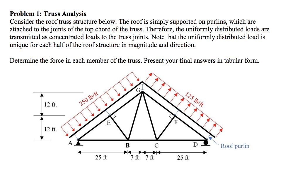
Solved Problem 1 Truss Analysis Consider The Roof Truss Chegg Com

Picture 1 Ideias Para Oficinas Arquitetura Pergola
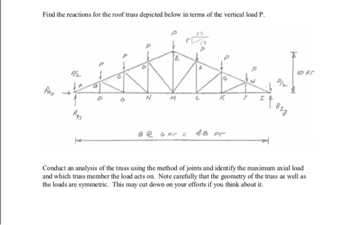
Solved Find The Reactions For The Roof Truss Depicted Bel Chegg Com
Solved Find The Reactions For The Roof Truss Depicted Bel Chegg Com
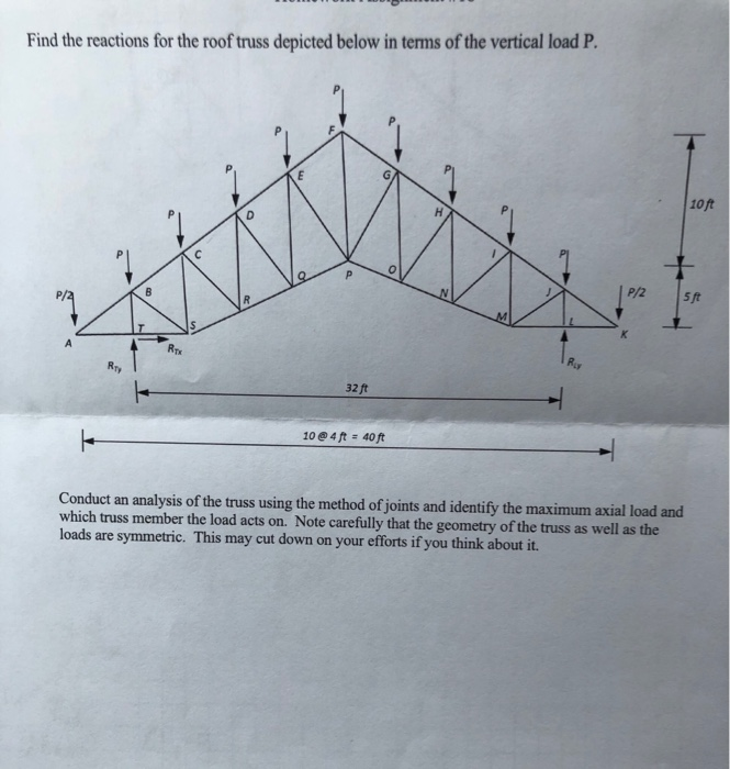
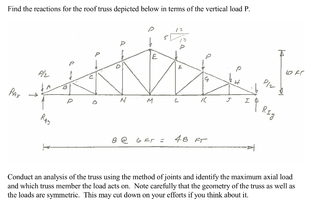
Solved Find The Reactions For The Roof Truss Depicted Bel Chegg Com
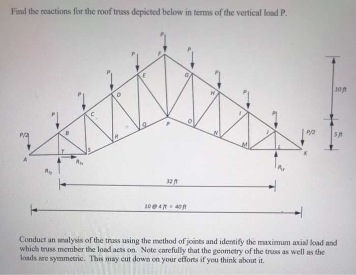
Solved Find The Reactions For The Roof Truss Depicted Bel Chegg Com
3 determine the loads on the roof truss based on the tributary area and the load path.
Finding roof loading on a truss at joints chegg.

Model Is Of Tension Trusses That Would Be Covered By A Hard Material Such As Ceramic Civil Engineering Construction Civil Engineering Civil Engineering Design
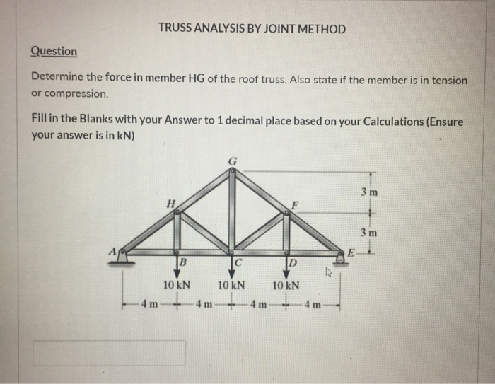
Solved Truss Analysis By Joint Method Question Determine Chegg Com
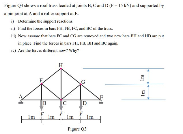
Solved Figure Q3 Shows A Roof Truss Loaded At Joints B C Chegg Com
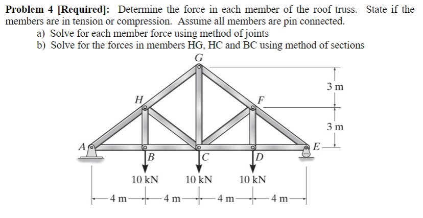
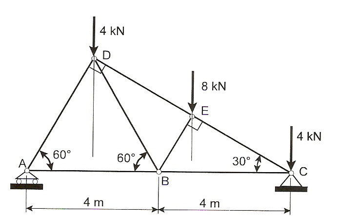
Solved Problem 4 Required Determine The Force In Each Chegg Com
Source : pinterest.com
